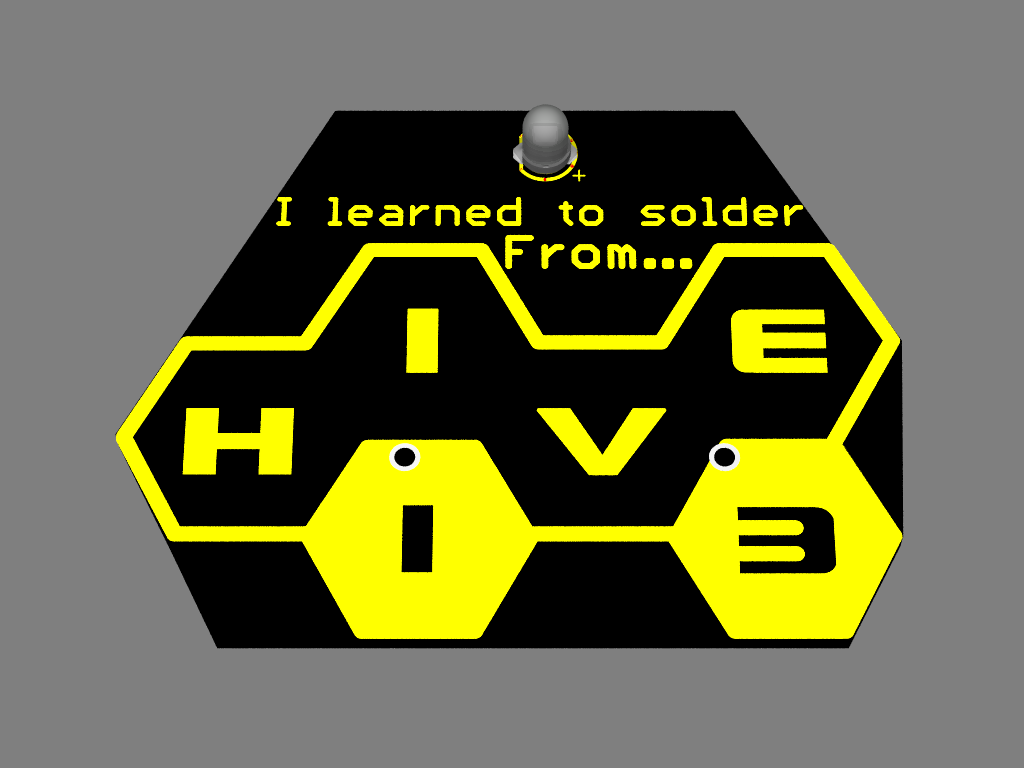
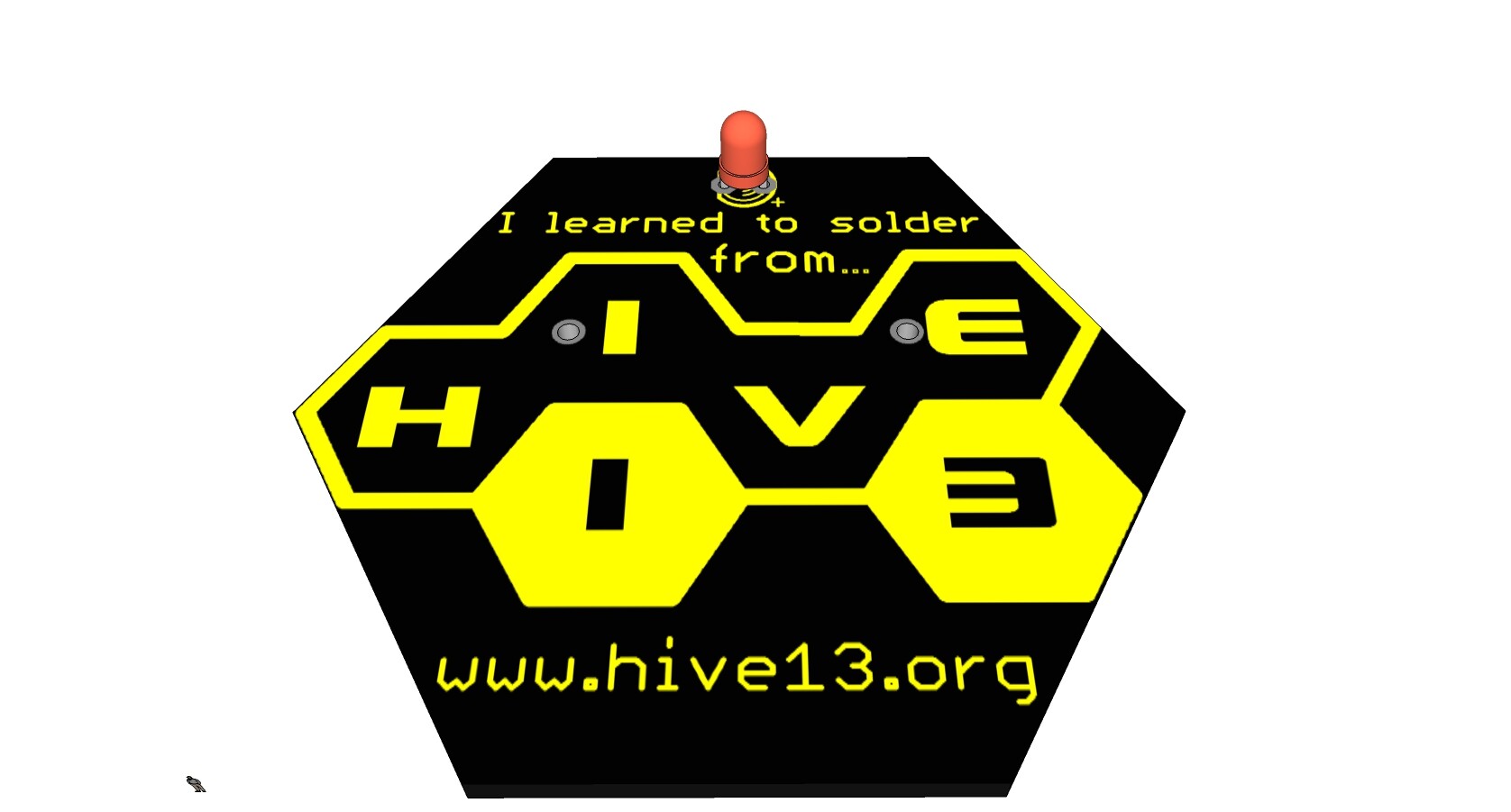
I made this 3D render yesterday to bring to the meeting, and then forgot to actually show anyone.
I’m not sure I like the shape, the only purpose of this version is to have a sanity check that 1.5 X 2 inches would work, so I can get quotes for that size.
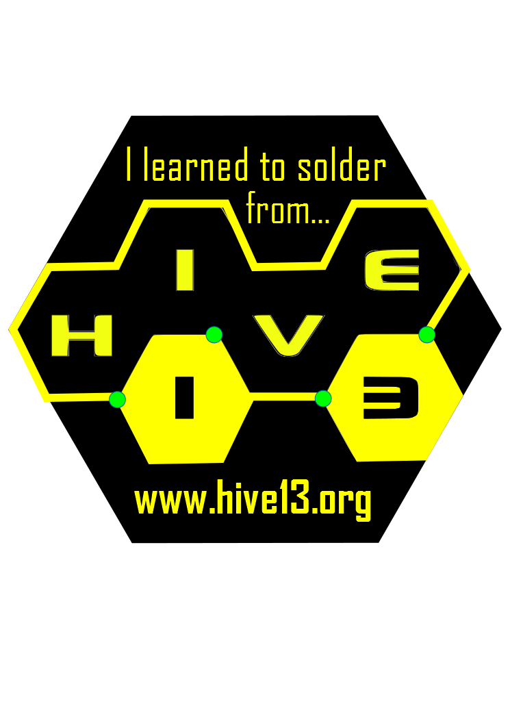
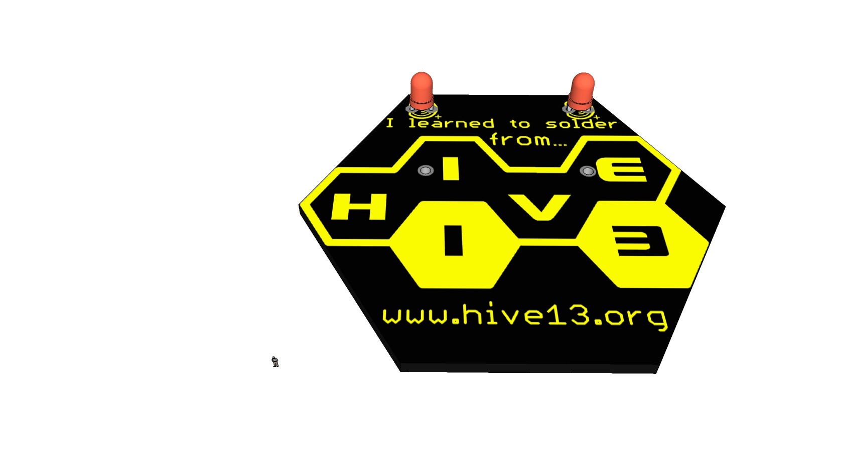
You are doing a great job with this project!! I love how you used the outside of the Hive logo for the edges! What if you used a whole hexagon? It would be a nice symmetrical badge, and there is room for our website. I am at work, so I could only mock up something quick! It would be more expensive though, because it would be 2x2. It was just a thought when I saw this
Unrelated: The svg version of the hive logo on the art page is sort of messed up (that’s why this badge version looks so sketchy). I have an svg version that is customizable for colour, lines, etc. that I can upload once I have my laptop at home.
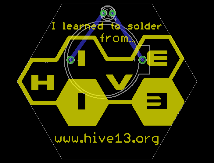
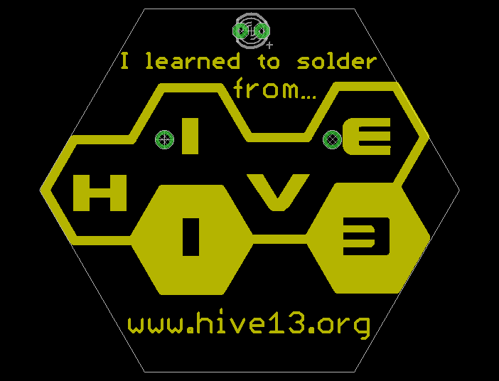
Also if we wanted we could have 4 LED’s (not sure how much more that would cost) placed at the corners of the logo like this. (Not that colour of course, but just so you can see what it looks like.) If we do only want two, I think rather than being in the center, we should place them on the vertices of the logo
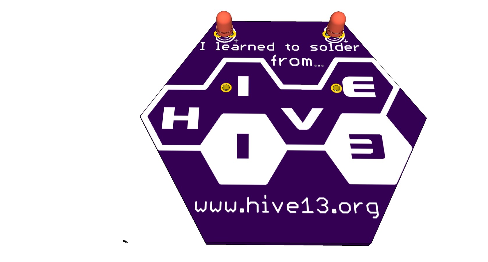
How about two LEDs, one at the top left corner of each yellow hexagon (it puts them symmetrically in the middle of the larger hexagon as well). This way a simple circuit would be the two LEDs and a battery, and a more complicated circuit (on the same board) could include an attiny to cap sense the yellow hexagons (“1” and “3”) to turn on/off their respective LEDs or do some other function. We could charge a few dollars more for the extra component cost and teaching time (to keep that line shorter) and still just ask for a $1 donation for the simple circuit.
I agree the hex looks much better. It gives you room to the url, and more room on the back for Dave B’s vision of a dual purpose more advanced board. I just finished updating the spreadsheet with 28 quotes based on a 3 square inch board, but now that I’ve figured out how to gather that information, it won’t be too hard to re-do them.
As long as with stay with the super simple version, (RGB led with blinking built in powered by a CR2032) batter, I believe we can only do one of these LEDs. But places for tiny surface mount LEDs could go in the vertices indicated and be referenced by any “advanced” circuitry.
I’m thinking of having a little pad that can easily be cut with a knife to disable the simple version, and some jumpers to enable the advanced circuitry.
The LED in my mockup is 3mm, so bear that in mind for scale.
I didn’t use the SVG version of the logo, I reduced the PNG version to a bitmap and then imported it into eagle cad. And then seeing how HORRIBLE the import worked, I traced over that layer using Eagle Cad’s tools. So any sketchiness is either my fault or Eagle Cad’s for it’s limitations. Or possibly an artifact of the 3D render addon I’m using.
To be fair, I didn’t come up with that idea. I heard it tossed around at last week’s meeting. Don’t wanna step on anyone’s toes acting like I thought of it first, haha.
re: cost… the price between the two would be so negligible that there needs to be some way to keep everyone from going for the more complex design and clogging up the lines. maybe an age limit for the more complex one? Or only two stations for the complex and many more doing the simple? or other way around?
The only reason to use the same board for the simple vs complex version is to reduce board costs. If we think we are only going to have a small amount of either one, there is no reason to double up.
Combined board pro:
cheaper to produce in quantity than two smaller quantity different runs. If we wanted 100 of each, it would cost a bit more than just getting 250 of a combined version.
flexibility, we don’t have to know how many of each we need for the board, we just for worry about parts inventory. All the parts I’ve looked at for the simple version are pretty close in price (on ebay) no matter what the quantity.
combined board con:
deadlines. I can have the simple board on it’s way to be prototyped tomorrow. The advanced version could percolate for a while.
detracting from the simplicity for the novice version. We’ll have to be saying “just ignore that bit” and “whoops, you were not supposed to solder there, let’s start again.”
Not sure if it’s a pro or a con, but the simple board has NO copper on the front side. This also opens up the possibility of using the copper layer (with soldermask not covering it) as a design element, a third color.
I’ve been assuming the more advanced version was for scheduled classes, the “show up at the booth” would be the simple version.
Looking at that render again, I’m almost certain the cruftyness is just an artifact from the 3D renderer, since the camera angle is from the side, something that may not be obvious because of the black board. I believe this because of the stray pixels on the sides of the H and the I, two items that are just rectangles that I’m sure I couldn’t mess up.
The original eagle file is all vectors, though we will see how it renders when I make a gerber file out of it.
I went ahead and updated the “sample to see how big it is” eagle cad file to look like Elizabeth’s nifty version.
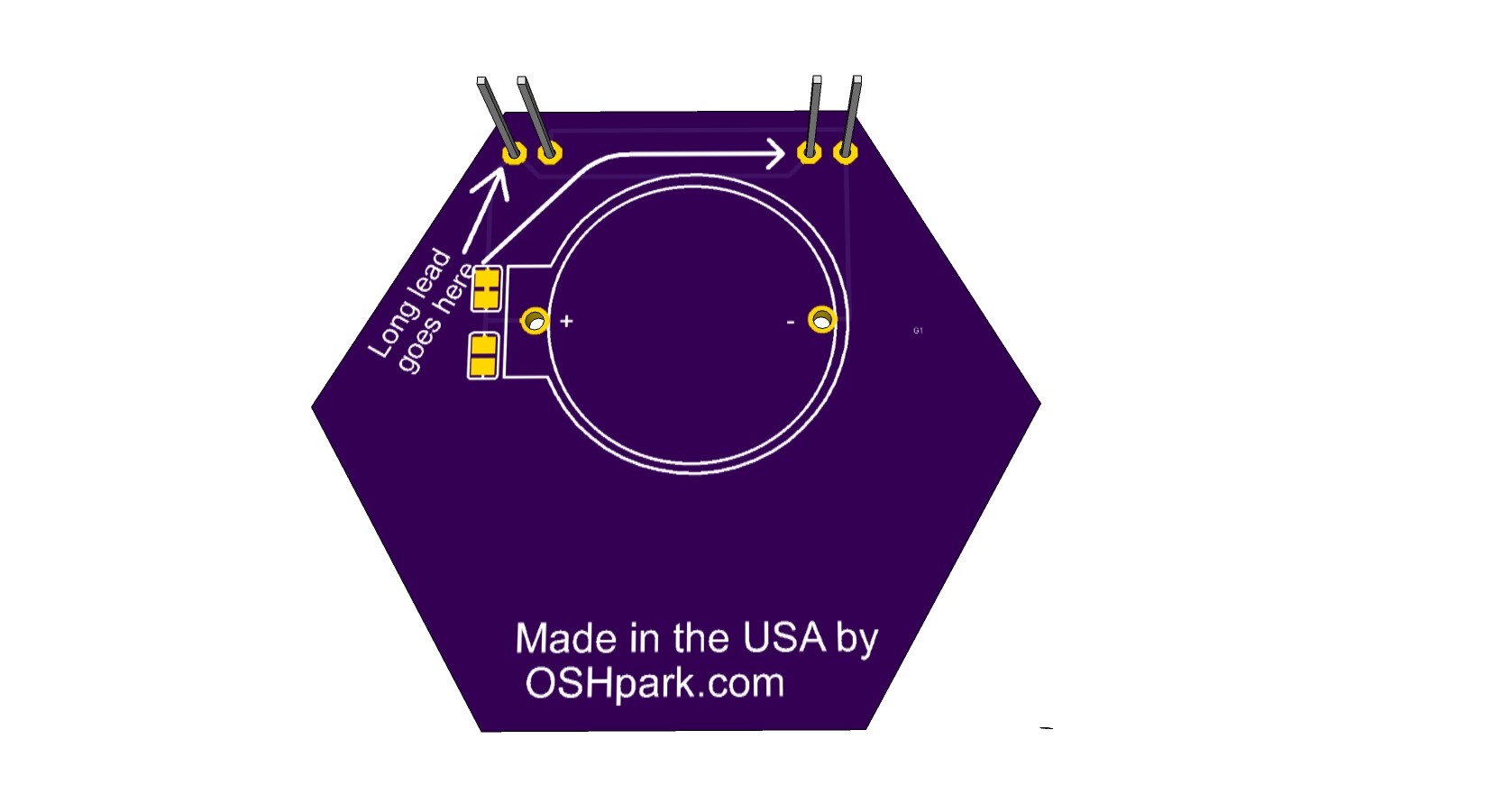
For some reason the 3D render plugin no longer works with this board, perhaps due to the complexity of the artwork, so I just exported a couple of views. The first is just the top layers and the other is both top and bottom so you can see how much of it is taken up by the coin cell battery.
My vote is for the combined hexagonal badge as well.
How exactly do we plan to have the full color hive13 logo put onto the board? Is this going to be a sticker applied to each pcb?
For the advanced version we could populate one of the 2 led footprints with a photodiode. Then 2 advanced badges can be held up to one another and exchange bits using the photodiode and led for rx and TX? Maybe this is beyond our scope, but it’s an idea.
It would also be neat to have a capacitive touch button under the 1 and the 3.
I was originally thinking a black board with yellow silkscreen. This wouldn’t cost much more in decent quantities from at least one vendor I’ve priced.
It’s just two colors. Ignore the green in the picture I posted, it’s just the default color Eagle had for the hole and I didn’t change it. Likewise the lines that show where the LED would go would actually be in whatever color the rest of the silkscreen would be. And are covered up by the LED anyway.
If we go with OSHpark (in quantities less than 1000 or so) it would be a purple board with white solder mask. I wouldn’t have a problem with that, I think it would look nice, but purple is my favorite color. See the separate thread on board houses.
If I can dig one up, I’ll bring in an OSHpark board to the next meeting. Failing that, there are lots of pictures online.
While you guys talk about the advanced version, (I consider it a separate project that will happen to share resources) remember that every component you contemplate going on the front should be considered in light of how it will look unpopulated in the simple version. They should be discrete and small if possible. In the picture I posted, there is only one LED footprint, those two other holes are where the battery holder is soldered on.
I’ll make another version with two LEDs to compare, and maybe let two LEDs run overnight on a single battery to see how well that works.
This badge is (currently) rather small, two inches wide at the widest point. This is because the goal was to have the kits cost us $1 or so. The simultaneous desire to not spend very much on the first run is incompatible with that goal, but $2.50 or so each for 100 is realistic.
I think the OSHPark version would look better if you make the Hive13 logo gold (i.e. make it a copper pour). It will also be SHINY, especially with a LED shining on it
Also, have you thought about adding a MOSFET to make a simple touch switch? Personally I like that better than having the LED on all the time.
I agree on the copper pour. But that may hamper the efforts of the “advanced version” team, since it would use up so much real estate on the front that could be used for routing signals.
If we decide to just abandon the dual purpose board and have two versions, we should definately consider using a gold top layer for all the artwork on the simple board. It will make it look more like a piece of jewelry!
I would consider adding a capacitive switch of some sort as something that would go on the advanced version and I believe it has been discussed. I know it’s not really an advanced concept, but the idea for the simple version is to have something so simple that anyone can have immediate success in just a few minutes. I believe anything beyond battery and LED(s) subtracts from that goal.
If you don’t know what I’m referring to by “simple version” and “advanced version”, see the thread with the subject “blinking badge - circuit simplicity”. I’m sure I have confused things by creating multiple threads.