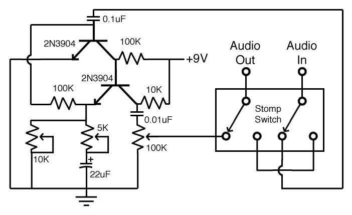
I’ve recently rekindled my interest in building guitar effect pedals. Along the way, I got this crazy idea that it would be cool to have a “fuzz”, or other pedal that can switch between two different types of transistors (germanium and silicon) using a foot switch. Why? Because the effect produced by each has different sonic qualities. The problem is, I don’t have enough knowledge to engineer this circuit. So would I have to create two boards and select the desired circuit via a switch, or is there a way to build one circuit that is able to switch between the desired transistor? I have attached a sample schematic for reference. In the end, I want to make the same circuit but switchable between 2 silicon and 2 germanium transistors.
Hmm, I think due to the different characteristics of germanium vs silicon transistors (base emitter voltage being ~0.1V rather than 0.6V), gain, and other such things you would need to switch in different bias resistors which is what most of those resistors are. For simplicity I would probably just put both circuits on one PCB and then just use a double pole double throw switch the switch the audio input and output between the silicon transistor circuit and germanium transistor circuit.
Just so I’m clear, you’re saying build the circuit twice on the same board, and switch between them. And I will need to use different resistors (higher value?) for proper biasing.
The circuit already has a clean channel, which is essentially the off position. Basically, I want to make one pedal that has both vintage (germanium transistors), and modern (silicon transistors) controlled by a separate switch. So one switch for on (fuzz)/off (clean) and one switch for the type of fuzz, vintage/modern .
As for biasing the transistors, every part number has different specifications. With a little digging to determine the configuration used in that schematic, and some biasing equations it should be able to plug in just about any transistor pair and get the right resistance values out.
I would roughly assume that the potentiometers used can be left alone, unless experimentation says otherwise. Finding a way to not need extra “pots” would be as pressing as finding the right bias resistors, if that’s what you want. I’ll do a little research and get back to you in a moment.
I'd prefer to not use extra pots if possible. If I'm being honest, this is just the start of a larger project. With that in mind, I'd love to know how to make the calculations on my own if you don't mind sharing the secret formula.
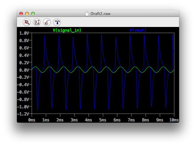
Ok, from what I’m finding this is a fairly simple two-transistor amplifier, which is supposedly “amazing” at amplifying a signal. Thing is, the values may be a bit funky for doing the job right, as it seems to give me some odd waveforms on the output in LTSpice. I’m wondering if it doesn’t have something to do with the frequency I’m inputting. *Nope, it was the fact that you’re pulling the output from the collector of Q2, instead of the emitter. *
I’ve uploaded an LTSpice file containing something that you can use to simulate the circuit. As for switching between outputs, I hadn’t noticed until recently that this was a foot-pedal. You can put one of those in series with another, if they hold their position, to switch between the amplifier sections. And while it would be cheaper to be able to re-use the potentiometers, it may be simpler to set things up with separate pots for each circuit. That way you can tune each circuit the way you want, and leave it there.
Try playing with the circuit in LTSpice, to see how it reacts. I’m not sure where to go from here myself, not being an audiophile, or especially practiced with transistor amplifiers.
I told a musician friend about this topic, and he suggested that you might want to check out http://www.beavisaudio.com , nd about It has all sorts of information that might be helpful to you… He said “it sounds like he’s trying to make an effects pedal”
For what it’s worth, the pots manipulate the sort of effect you get. The one on the the right is volume. The one on the left, I think adjusts the amount of clipping you get (strength of fuzz effect), the middle one, I think, adjusts the pitch at which fuzz kicks in. If I have guessed wrong, the adjustments of the left and center pots still have those effects as a pair, but one may need to adjust both to get the effect I claim for one.
I think the easiest way to effect the silicon/germanium switch is to make each circuit separately, but replace each pot with a ganged pair, with one in each circuit.
Eliminating any of the pots means giving up an adjustment.
µF = uF in a lot of hobbyist level schematics. For your purposes, as long as the simulation still works, it doesn’t really matter. If I were to get technical, “µ” would be the one to use because it is the scientific abbreviation for “micro-” as in “micro-farads”.
You’ll also notice that I used two fixed resistors to simulate the volume output potentiometer, and added a very low resistance resistor onto the emitter of Q1. The low resistance resistor can be ignored, I was trying to figure out if biasing the emitter of that transistor would ultimately affect the circuit. In simulation, you can do that by removing it and reconnecting the wire segments, or by setting it to a very very low resistance, such as .001 Ω ( 0.001R in LTSpice ).
The input voltage source, was probably set to frequency response testing when I posted that file. It’s not a big deal, but can be useful when finding out how the circuit responds to various pitches and tunings of your guitar.
I noticed LTS seems to accept u as µ.
I've always been interested in electronics, but never took the time to learn it properly. In the past, I would just build from kits, or copy someone else's project. But now I want to go deeper, and modify some existing circuits. This all sprouted from someone asking me to build a kit for them, which started the ball rolling.
I know that I started in a similar way. My first involvement was 4-H Electric. After which, I realized that I could build electronic circuits, and decided to learn more about them. They fascinated me, almost as much as the AI research being done at MIT with the C.O.G. project at the time. I had already come to the conclusion that understanding software would not be my strong suit, and I didn’t want to be a carpenter like my father. But electronics seemed perfect. All software needs hardware to run on, this hardware needs power supplies and other support circuitry, even if it’s a programmable digital system. As such, there should always be a need for electronics hardware designers right? Little did I know that soon being a hardware designer would require being a code monkey as well, at least in the bigger, high paying fields.