Milling Aluminum on the Big CNC

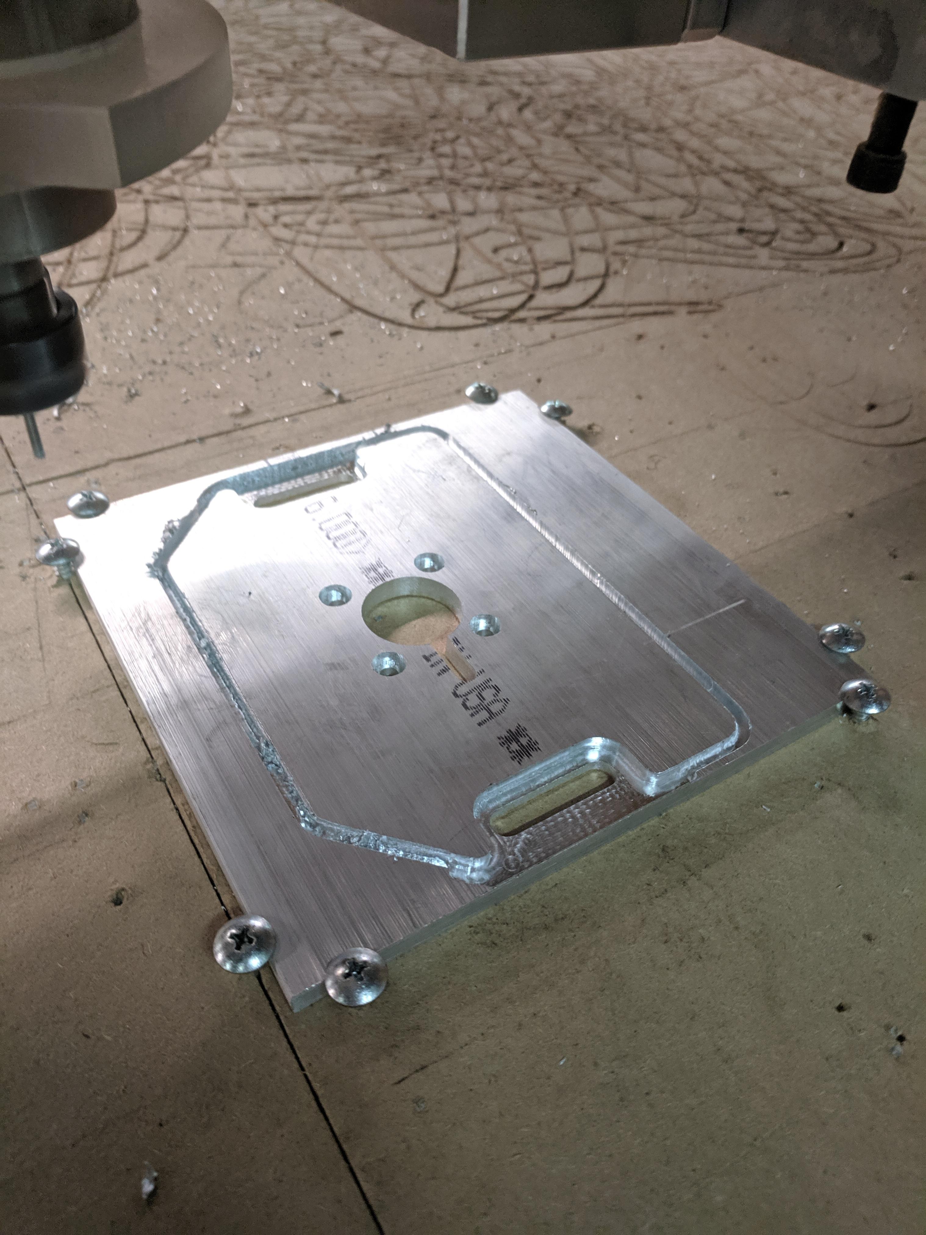
Bottom line: It works! (part is the motor mount for the Roland CNC’s new spindle motor)

I was a significant learning experience though, so I figured I would share my experience in case anyone else wants to try.

I tried it out last night, and figured I would share my results in case anyone else has wanted to make part out of aluminum but been scared to try

The photo above shows both the good and the bad if you look closely.

I started milling the holes and slots/pockets, all of which were wider than the 1/8" end mill I used. these featured milled very nicely, there was little to no chatter, the part stayed cool, and the surface finish was nice. The cutting parameters I was using were:

1/8", 2 flute, Carbide Endmill
24000 RPM spindle speed (~786 SFM, would have done 800+ SFM, but 24000 RPM is the big CNC spindle’s max speed)
140 in/min feed rate (~.003 in/tooth, 2-3% of end mill diameter)
.0125 in depth of cut (10% of end mill diameter)
.050 in stepover (40% of end mill diameter)

The problems only started when it came to cutting the part outline to separate it from the plate (not pictured, but before it cut through, I put screws in the holes already milled). The outline cut was a full width of the cutter slot, and this very rapidly lead to heat buildup and I started having chip welding to the endmill and to the cut surfaces of the slot. The part got VERY hot, and the surface finish was terrible on this cut.

I may have been able to avoid this by slowing down the spindle speed and feed rate and/or using coolant (though, probably not a good idea to use coolant on a CNC used for wood). Based on how nicely it cut everything other than the endmill-width slot, I think the better option would be to simply forcing it to cut a wider slot when separating the part from the stock. In V-Carve, this could be done by offsetting the outline vector outward by 1.9x the endmill diameter, and instead of using the profile toolpath, use the pocket toolpath option to clear the full space between the two vectors. this would force the router to cut a groove 1.9x the endmill width with two passes around the part for each step down. While this may take a few more minutes, it gives space for the chips to evacuate and prevents the endmill from rubbing on both sides of the slot and overheating (The extra time should not be a big deal either, the part pictured above was only 16 minutes of machine time).

Using a better program for toolpath generation (Fusion 360, mastercam, etc) would also give the option of cutting the outline with a trochoidal toolpath, which would be even better at ensuring the chips had good clearance for evacuation

Anyone have more experience with doing this and can point me to other ways to make this work better? Anyone have any aluminum parts you want to mill? It’s exciting to know our CNC can do it!

Thanks,

Kevin McLeod
Woodworking Warden & Secretary
Go you!
-D

IMG_20190819_212008.jpg

The Joe’s CNC forum has covered this in detail and has some great info for good cuts on our machine.

Coy

IMG_20190819_212008.jpg

An MQL system like a fogbuster might work without getting coolant everywhere. Otherwise just an airblast can be useful.

IMG_20190819_212008.jpg

The Joe’s CNC forums appear to be pay-to-play?

I’m well aware that info on the topic is out there on the internet, I was more putting this here so our members who might not have thought about it would know it’s possible and maybe not as difficult as might be expected.

I did find that our CNC appears to either have a z-zero offset problem or a z-scaling issue while making this part. I intended for the counterbores and clearance around the slots to be .125" deep, and they ended up >0.140" deep. the first pass didn’t seem too deep either, which makes me think our Z steps/in setting needs calibration.

I’m pretty sure any liquid coolant on that CNC is a bad idea, but the air blast could definitely be nice to help with chip evacuation, even when cutting wood or MDF (sometimes the groove gets packed with the wood/fiber chips). Maybe I’ll put some thought and effort into adding an air blast attachment at some point (just what I need, more projects).

Awesome!

Most things seem impossible until someone does it. :slight_smile:

I have seen 1 flute mills recommended for stuff that melts, e.g., Al and plastic.

I agree that coolant on the CNC router would be a bad idea!

Air blasting could work. (Remember to vacuum up what the DC doesn’t!)

I didn’t use the shop dust collector, because I know some people have issues with metal being sucked up in it.

I babysat it with a shop vac just following it by hand.

have you seen the attempt from years ago? i believe the large aluminum sheet is in the metal room :slight_smile:

Hive13 has a login to Joe’s forums. Joe himself cuts the aluminum plates he sells without using coolant.

Coy

So, I got this part installed, and while it is close enough to do it’s job, installing it did reveal some things about the quality

When I set up the tool paths, I interpolation milled the counterbores and then in another operation, came back and did the same for the through holes. when bloting up the motor it became very clear that the hole pattern was not quite right, it was supposed to be a four bolt pattern with each hole equally spaced, but the through holes are definitely closer together in one direction than the other, indicating that there is some calibration necessary on our steps/distance settings. The counterbores were also not perfectly concentric with the through holes, which is a slightly more confusing problem. There are several things that could cause that, with backlash and skipped steps being the most likely ones in my mind. I watched the whole cut, and did not notice anything that sounded/looked like it caused skipped steps. However, the misalignment seemed greater than backlash would account for, and I would have thought backlash would cause other problems (say, in the circle bore or the slotted hole recesses).

Any thoughts?

You are on the right track. We can talk tomorrow night.

Once the capability of the machine is determined you can design for manufacturability within those tolerances.

This would be a good example of measuring process capability. CpK. After a few cups of caffeine I might be inclined to crank through the analysis.

Ugh, that used to be something I even taught.