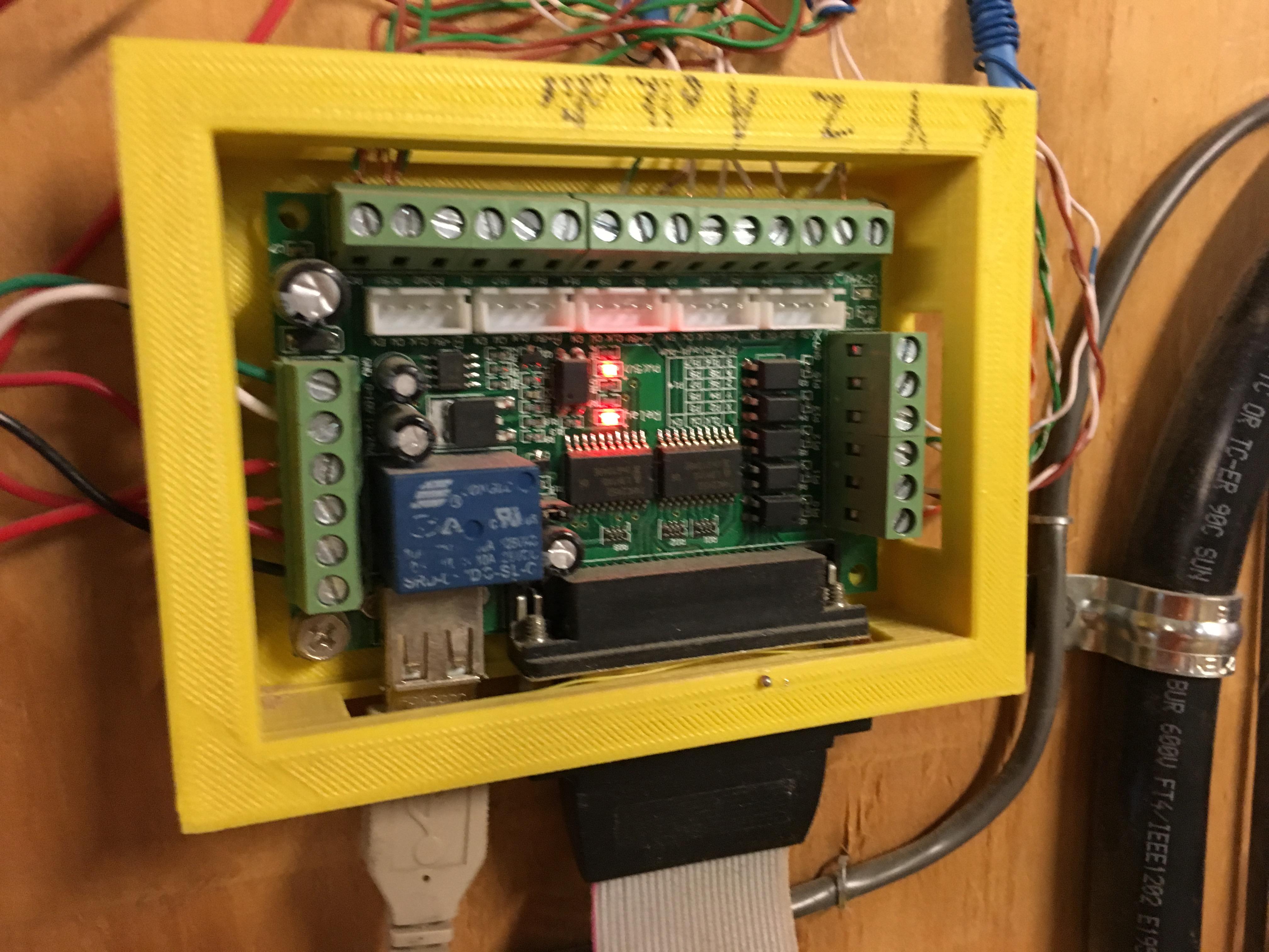
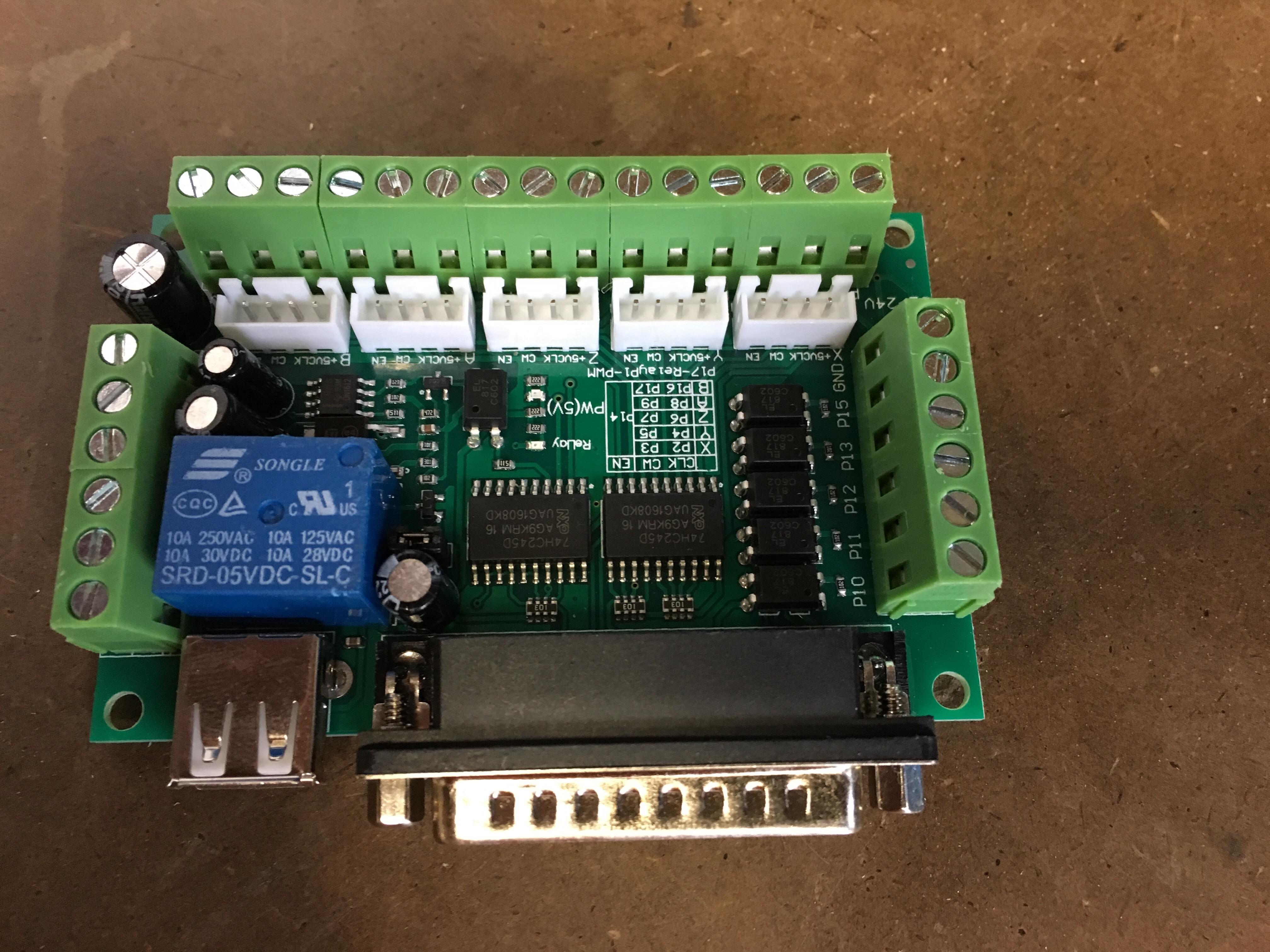
Does anyone still have the breakout board case that was designed and 3D printed for the Large CNC?
I would like to add an additional breakout board to the Large CNC and just trying to prevent reinventing the wheel, Please see the attached images old and new board.
Didn’t know a camera was purchased. I may have an extra. What’s the added breakout board for? I am looking for a 4th axis but I planned on using the same board.
The camera that was purchased for it was under the Red Vending machine, along with a monitor mount and a few other things. It’s keyed to the rest of the vending machines, so anyone with the Medco key should be able to get you in.
Short story: I am planning to add a sensor to see the spindle speed.
Long story: I spoke with Jon and mentioned the spindle problem and he suggested connecting it to the VFD
I was looking at the original VFD manual that was posted in the wiki and I saw a programmable output which included the calculated spindle rate. He said there was no additional connections I could use so I would need an additional breakout board, male to male usb cable, usb power supply for the board and a female to female parallel to 26 pin cable. So I ordered the above and when I started looking for the specific pin outs on the VFD that were in the manual I was unable to locate them. After further research I learned this VFD was indeed different than the wiki. Then after looking at the new manual I learned there was no rpm output. So now the plan is to run a hall effect sensor and get the spindle rate to report it back to Mach3.
If my memory serves me correctly there is an easier way. I thought I remembered reading somewhere that you could adjust the PWM curve by manually entering speeds at different currents. Is this exact no, but you could enter in values every 100 RPM which would get things very close.
With that being said feedback is the best way. Can you send me the new manual you are referring to? I remember reading this manual several times and could have sworn there was a way to get RPM feedback.
I may be mistaken and thanks for double checking for me if I can do it an easier way I’d love to!
Lauren and Coy,
Even if we can get the VFD to output directly isn’t this still just a calculation in which could be incorrect under load? http://www.exoror.com/datasheet/VFD.pdf is the manual I located for our model.
I would think the name of the game would be to get your RPM and feed rates so that you would NOT be lugging the motor and causing a significant change in speed. If you could sample the shaft speed fast enough, this would probably be a great way to fine tune your movement rates.
-D