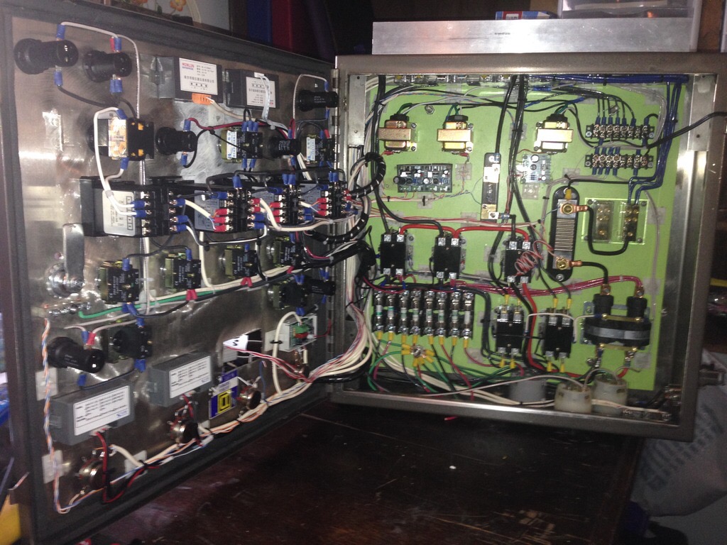
I did some work at the Hive this afternoon to dig through the industrial automation stuff that Sean graciously donated. I’ve started to salvage and separate/catalogue some of the gear. Most of it is DIN rail stuff, which is very useful.
Some of the stuff is very cool and some of it is not as useful as I thought.
Since the original system was setup for 240V, most of the stuff that runs on AC I don’t think we can use. I will create a box for the 240V stuff and label it so.
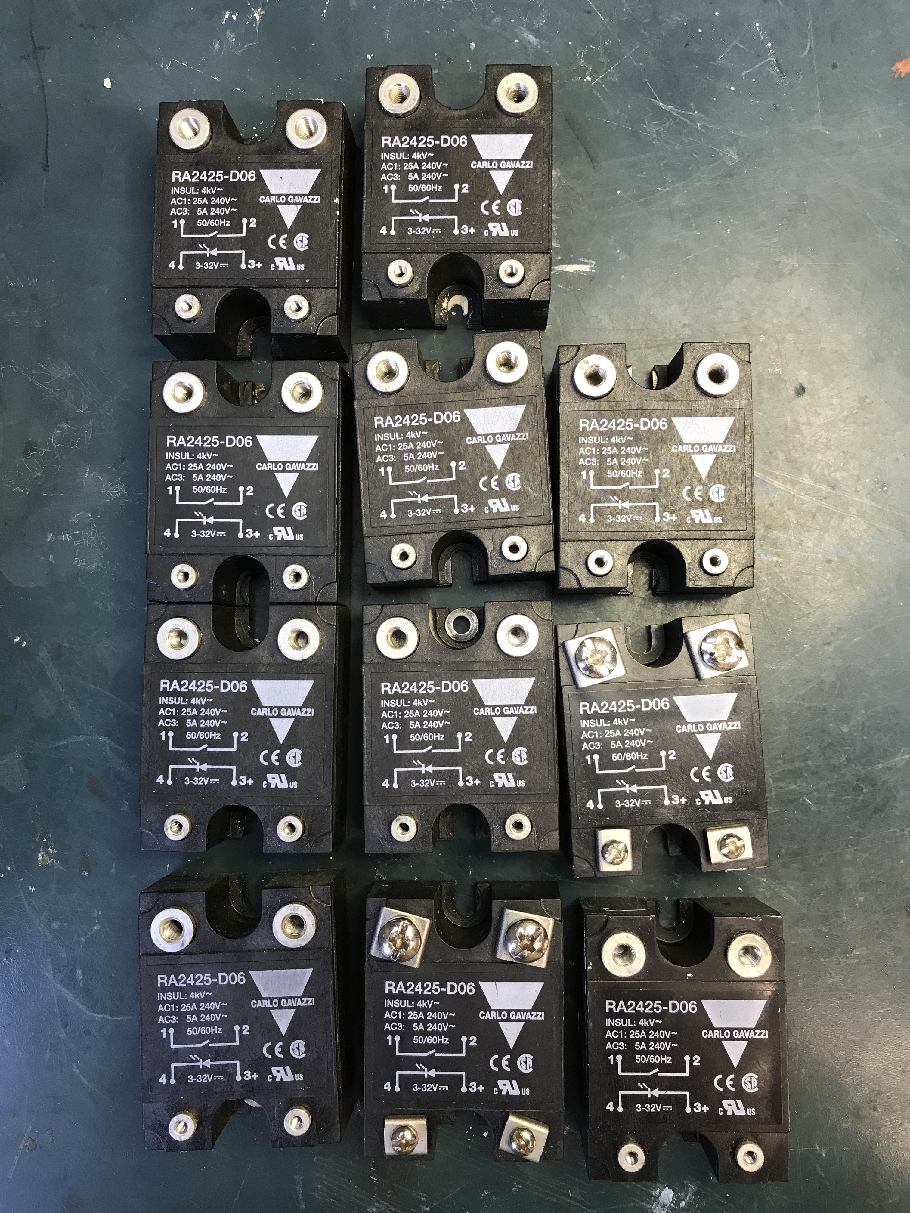
There was 11 solid state relays but they are 240V 
I did find one Siemens 24V/10A power supply that can be converted to 110V. 
I’ll try and separate them into relevant boxes with labels and create some kind of spreadsheet with all the parts. This could be great for some automation stuff.
If the boxes and parts are in anyone’s way just move them onto the floor under the workbenches. I hope to get it cleaned up in the next week.
Thanks again Sean,
Welcome, I'm sure I'll find more stuff to rumage through as they are clearing out spaces. I'm surprised though the relays didn't take a 24v DC trigger voltage. Of course I didn't look before hand either.
I think they are 3-32V DC on one side and 240V AC on the other.
Those are SSR’s. The polarity of DC or insufficient load on either side might be the issue. They often fool multimeters, as they don’t appear as a closed circuit to DC. They are made for AC loads…
From: Brad Walsh
Sent: Saturday, June 3, 2017 12:39 PM
To: cincihackerspace@googlegroups.com
Reply To: cincihackerspace@googlegroups.com
Subject: Re: [CHP] Industrial automation donation
|
SaneAttachments has copied these files to Dropbox
| ![SaneBox]() |
|
IMG_0724.JPG
Dropbox/SaneBox/Brad Walsh/Re_ CHP Industrial automation donation, 2017-06-03 12.39.04 PM/
Note: SaneBox was unable to remove all of the attachments and as a result the original files are still included.
I think they are 3-32V DC on one side and 240V AC on the other.
Dang! Those are used in beer brewing controllers! Anyone feel like wiring up a controller? Lol
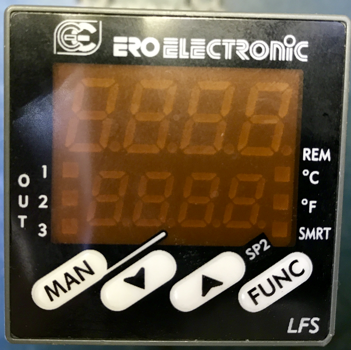
There are four temp controllers in the box of goodies if memory serves. Just lacking a thermocouple or RTD 
Yep, and that is due to the nature of how they operate. A small leak current will be present through them in their off state so they are never truly “open” in a sense like mechanical relays would be. Rather the resistance across the terminals just becomes very high in the many mega ohm range with the on state changing to a low resistance value. But they certainly come in handy for PID control loops where power is being switched on and off rapidly such as a heater or other resistive load. The data sheet for the above are attached.
But they do manufacture ssr’s for DC usage too but haven’t seen any of those laying about yet given most of the stuff around the plant are ac heater control circuits for the various heated vessels and thermoforming machinery.
The only caveat being when an ssr fails it’s usually failed “On” so best to build in a logic controlled contactor or thermal switch upstream of the ssr.
RA2410LA.pdf (122 KB)
Did some more sorting this afternoon.
I put the interface display, breakers and most of the power supplies in a separate boxes.
There was a whole bank of safety circuit controllers. I’m not sure if we could even use them.
I’m thinking perhaps a box of high voltage stuff as that would not be as useful
When I get done sorting everything I’ll get a list together and we can decide what stays as Hive supplies and which stuff not to keep. I’m guessing Sean could eBay some of the stuff.
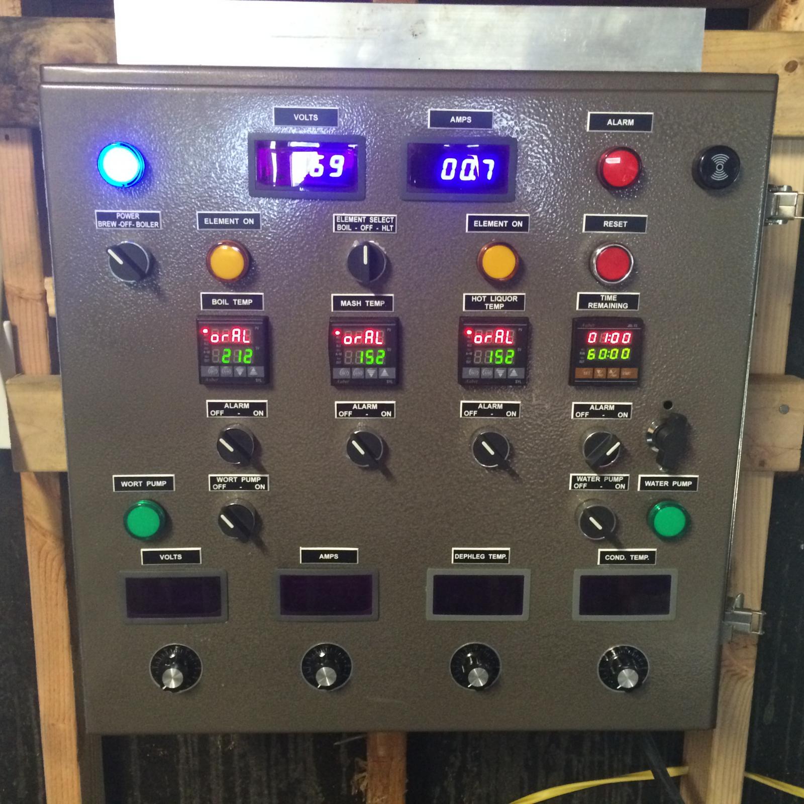
here is an example of a homebrewing controller. Its crazy! i actually have most of the components to build one, just haven’t taken the time to do so!
Ah, impedance, my old friend…
We should get cracking on some electronics courses… I’m hoping to have some time for some in July…
From: TechArtGuy
Sent: Saturday, June 3, 2017 2:03 PM
To: Hive13 Hackerspace
Reply To: cincihackerspace@googlegroups.com
Subject: Re: [CHP] Industrial automation donation
|
Yep, and that is due to a small leak current through them in their off state so they are never truly “closed” in a sense like mechanical relays would be. But rather the resistance across the terminals just becomes very high in the many mega ohm range. But they certainly come in handy for PID control loops where power is being switched on and off rapidly such as a heater or other resistive load. The data sheet for the above are attached.
All of that looks verrrrrry familiar.
Lorin,
I’d love to learn some electrical basics! I’m such a novice!
Tiff
Off hand I don’t know any reason you couldn’t use the 220v SSRs with 110v. If the situation was reversed then I wouldn’t try it.
Yep, and with the ones shown in this thread the spec sheet lists a range of 24-280 VAC. Anything less than 20V won’t go through and anything higher than 650V suffers dielectric breakdown. It has up to 32V reverse voltage limit on the dc control side with a control range of 3-32V. So you can switch them using a fairly low input voltage. If using a PWM, a control pulse width of .5ms or greater with a half cycle response and drop out time. Minimum switched current is 150 mA, device rated for 25A rms. Overload of 55A for 1s. Max inrush current of 325A for 10ms.
The leakage current I mentioned earlier for these are 3mA in the off state with a 1.6V drop in it’s on state. Won’t go in to the heat sinking requirements as that will depend on the load being passed through it.
Cool, so these could be used with 110v heaters.
I’ll put them in a separate box, right now they are lumped in with the breakers.
I think I separated 4 of the temperature controllers. Sounds like they would need some temperature detection inputs to work (RTD, thermocouple, etc).
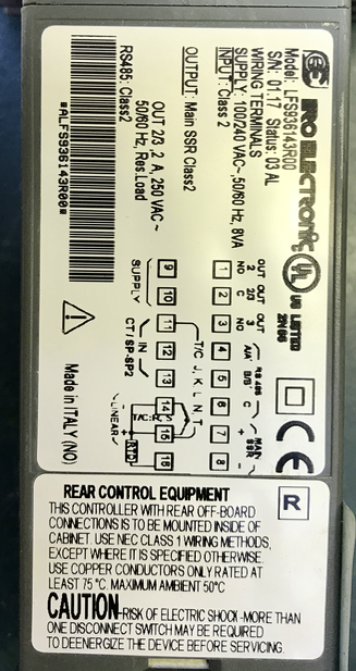
In regards to the sensing elements, currently those are configured for a type J thermocouple. (use the same controllers on two other lines). So if you have a process can tolerate a +/- 2.2C error then they can be left as is. Otherwise if you want the higher accuracy of an RTD that parameter will need set. My guess would be a pt100 or pt1000 rtd element would be needed of whichever grade is required.
I’ve attached the datasheet and user guide for the controllers. The outputs consist of dry relay contact Outputs 1 & 2 250V 3A resistive loads, inductive loads can be switch as well but have different limits based on the resistance. It will power an ssr on outputs 6 and 7 in two voltage ranges depending on it’s logic setting. I would guess they are 24V output as that’s a typical control voltage for many industrial applications. Though outputs 6 and 7 are not isolated internally so best to place an opto isolator between it and the ssr as a safety measure. They will also do serial communications over an rs485 interface if you were setting the SP and reading the temp via another controller such as a plc.
lfs_data.pdf (284 KB)
170.IU0.LFS.0D0.pdf (1.49 MB)