Thanks for offering help last night on the custom circuit boards for
the Galileo project. I have added the design sketch and some
reference links at the very bottom of the project page at:
Let me know the progress and I'll get the needed twelve TLC5940 chips
in the smaller surface mount PWP package (or even smaller RHB
package?) rather than the NT package (28-pin DIP). Note the thermal
pad on the bottom of the smaller chips. Will that be a problem?
I stayed up late with Clyde last night and we laser-cut all 24+
acrylic wiring block parts on his machine. They came out really
great. More details on that later as assembly progresses towards the
Detroit Maker Fair on July 30-31 at the Henry Ford Museum.
Thanks for this good start Dave. I'll ID more of the 7-pin header in
a next post and start on the parts order list. Help me on the surface
mount part numbers for R1, R2, C1, C2.
R1 r2 are your currrent sense resistors. 0603 package. It didn’t look from the datasheet like there was a lot of power dissipation on this part but I may be wrong. C1 and c2 are power decoupling caps figure 0.1uF ceramic 0603
Don’t worry about parts yet. Worry about which signals are needed on the 7pin so I can finish. I have 5 already
Vcc
Gnd
Sck
Serial in
Serial out
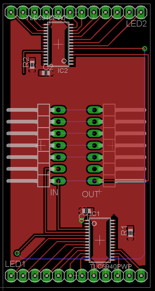
Done, at least with first revision. Board + schematic consistent, good DRC, ready to rock.
Board size = 1.25" x 2.00"
ground pour on top layer, VCC pour on bottom layer. Power traces are 0.012
My only question would be do you want the 12x1 connectors moved in at all? They’re about 0.025" from the edge of the board right now. I could probably bring them in a little more if need be without any fuss. Board could be made shorter. More than a 0.25" shrink would be a little painful. I could get them super fucking small doing double sided components if need be.
Many thanks for this effort. It may need some switch-around work.
Are you still in for this?
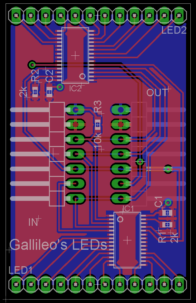
The physical layout (mating connector plan) anticipates the LED1 and
LED2 headers with LED1 on top, LED2 on bottom, and both with pins
sequenced the same 0, 1, 2, ...,11) from left to right. Also the
components in the 1.25" x 2.00" board size are OK, but we can/should
make the board 0.50" taller; with 0.25" bare board above the highest
component, and 0.25" bare board below the lowest component. This will
leave a tab at the top and bottom for intended mounting slots at top
and bottom.
What will be the next step and timing to get (at least) six boards
actually made per the final design? I'm also looking into the Digikey
part numbers for the component order.
Take a look at these. Should be damn close. Might change caps resistors etc from 0603 to 0805 depending on what I have in stock. I still have to solder two ECUs tonight so I’ll check on that later.