Ok here goes My arduino wiring
Thanks Marcus and Ryan for helping
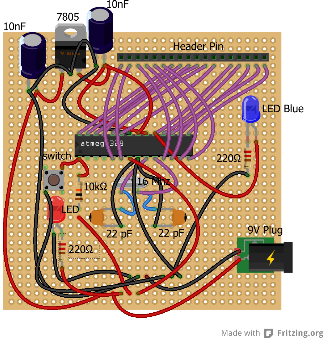
I created this is fritzing, I am sure i have made some mistakes, please can one of you experts review and note any mistakes or enhancements.
Thanks
Ardunio_v.03.fzz (16.2 KB)
Ok here goes My arduino wiring
Thanks Marcus and Ryan for helping
I created this is fritzing, I am sure i have made some mistakes, please can one of you experts review and note any mistakes or enhancements.
Thanks
Ardunio_v.03.fzz (16.2 KB)
It’s hard to tell which wires are connecting under the board and which ones are not, so I can’t say for sure. Assuming all of the red wires on the bottom are 9 volts and connected to each other and all the black ones are ground, you do have a miss-connection on pin 7. You have it going to the 9 volt power, it should be to the 5 volt power off of the voltage regulator. Like you have going to pins 21 and 20, which are correct.
Ditto with the 9 volts going to the reset switch and pin 1. It should be off the 5 volt bus at the top. The only place you want 9 volts (except possibly the exception discussed below) is to the voltage regulator.
Is the red LED meant just as a power indicator? Always on when the power is on? You have it hooked up to the 9 volts as well, so it should either have a bigger resistor, or be hooked up to the 5 volts from the voltage regulator. You can find appropriate resistor sizes from http://ledcalc.com/. 220 will be more than enough at 5 volts, but it should be 350 if you leave it at 9 volts.
Other than that, it looks fine.
One other observation. If you never intend to reprogram the chip and only use it with the blue LED, why bother with the header pins? Or do you plan to remove the chip and program it elsewhere every time?
Never mind about my last question, I see that it’s for a cube, so you need all those headers for the cube LEDs.