Air Compressor Status Update (NEED VOLUNTEER)

For those of you who have not already seen in slack, I spent last evening trying to get the air compressor back running. Ultimately, It got way to late and I had to leave without it fully complete, but it should not be hard for someone to pick it up where I left off this weekend. If you have ANY familiarity with electronics, you should be able to finish it up from where I left it. I will not be able to be back in till Tuesday, so if someone could please work on it this weekend, it would be greatly appreciated, as this is a pretty important part of our infrastructure.

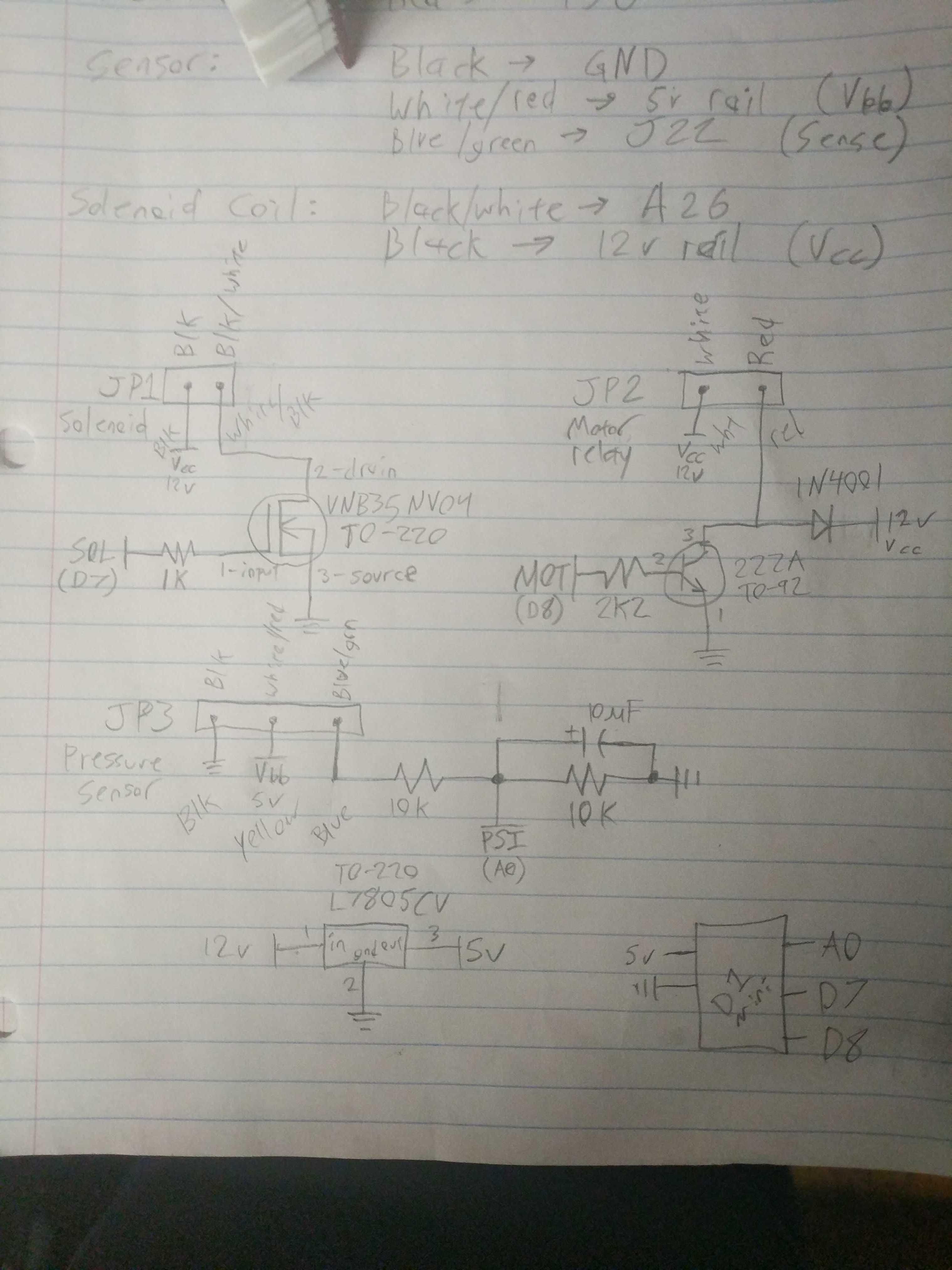
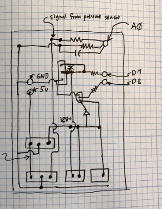
I started by working from what was on the breadboard to reverse engineer a schematic for it, turns out it’s a pretty simple thing with basically two power switching outputs (one for the head relief solenoid, and one for the motor relay) and a single analog input from the pressure sensor. There was also a simple power supply to provide 5v to the microcontroller and pressure sensor. The relay and solenoid both operate on 12v from a laptop power supply

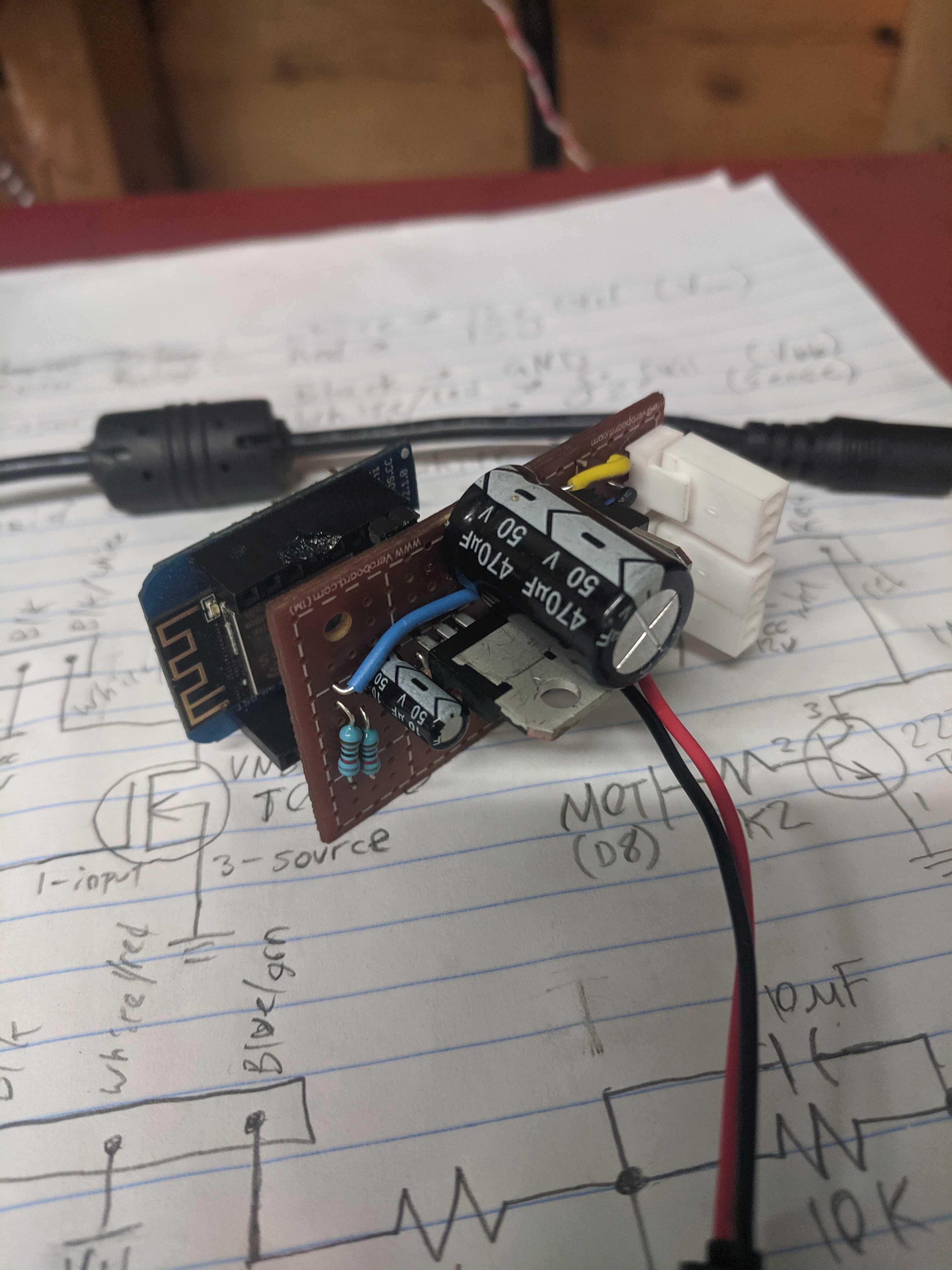
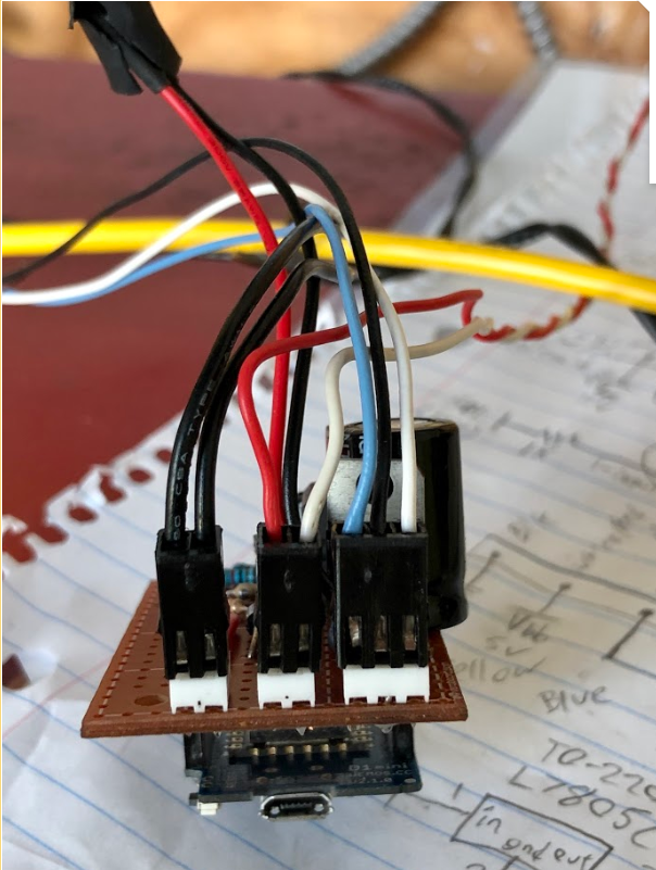
I soldered up all of that onto a perfboard (poorly, because this is not my thing), but was unable to test it all before I left:

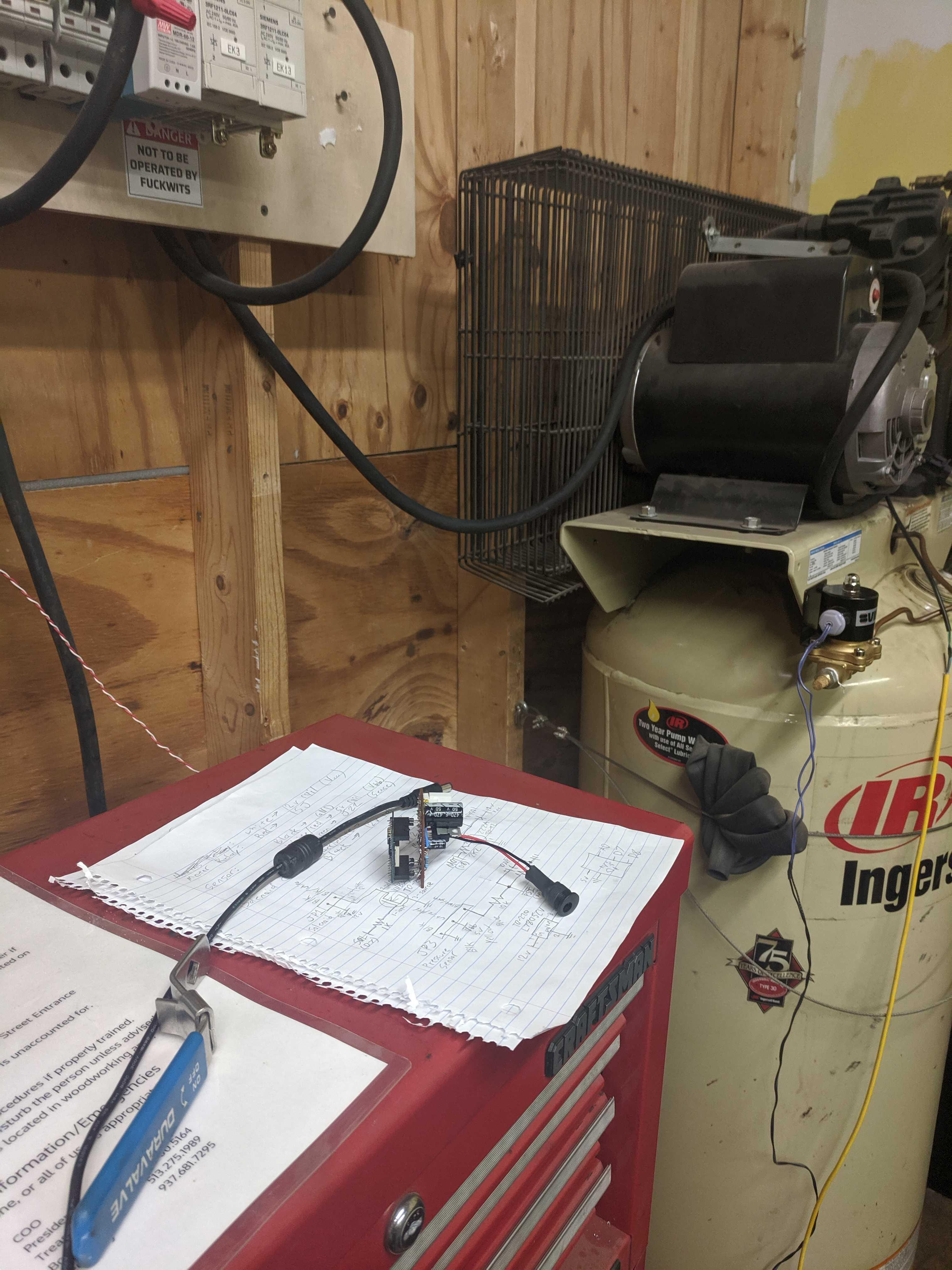
I left the board and the circuit diagram on top of the Lathe tool chest near the air compressor:

The only things that still need to be done are to put connectors on the solenoid, relay, and pressure sensor leads and plug it in and test it to make sure it works.

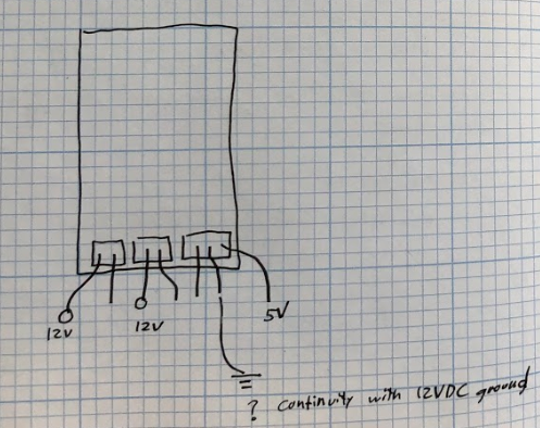
The connectors are the same ones used for 2 and 3 pin PC fans, I have the housings on the headers on the perfboard, but someone will either need to find the pins to primp on, or steal some connectors with leads from some fans.

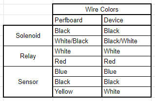
I ran colored wire to each of the headers on the perfboard, the connections to the devices should be as follows:

Untitled.png

Once those are hooked up, connecting the 12v supply to the barrel jack should cause the air compressor to begin to cycle, once it reaches 175 PSI, the motor should stop, and the solenoid valve should release a small burst of air to relieve the pressure on the piston head. It should then idle till the pressure drops below some lower set point (~125 PSI I think?), at which point the same cycle should repeat. The microcontroller also prevents the cycle from running during quiet hours, so if you are testing it out, be sure it isn’t quiet hours.

Thanks in advance to whoever picks this up from where I left off. Hopefully someone can finish it off and have it running tonight or tomorrow during the saturday cleanup.

Thanks,

Kevin M.
Secretary & Woodworking Warden

These are the connectors, if anyone has pins for them, please bring them in, as I am not sure we have any at the hive.

https://www.moddiy.com/products/modDIY-Female-3%252dPin-Fan-Connector-%28Molex-%232510%29-with-Pins.html

https://www.moddiy.com/products/modDIY-Female-2-Pin-Fan-Connector-Molex-2510-with-Pins.html

I just saw on Slack that someone said the air compressor’s safety ground wasn’t connected to anything either…

Can someone also please also make sure that a safety ground connection exists between the power cable and the compressor tank/motor/body? It’s not safe to have a 30a 220v metal machine running with no safety ground… please check this before doing anything else.

I’m doing a half-day vacation today since it’s my birthday weekend

I will head down to the hive and see if I can finish this up

Thanks brad!

I tried to get things going but something is still wrong.
I mounted the wires into the connectors (of course the inserts we have don’t fit the white connectors you had, so I used the black ones in the box. Ever so slightly too big).
I tried using the oscilloscope to do a benchtop test but it never seemed to work. I think it might need a load to pull some of the signals.
Once I hooked everything and plugged in the power supply (no compressor power) nothing caught on fire so I then unplugged the power supply and plugged in the compressor and then connected the power supply to the board.
The compressor fired up! It ran up to about 100psi and I stopped it (unplugged the board power supply) because I was a bit nervous about things getting pressurized without checking things out. I gave everything once over and then plugged in the board power supply. The compressor tried to turn over and then the breaker tripped. I don’t think the head vent solenoid is firing.

image.png

I also tried to trace out the prototype board so understood the wiring. Here is my crude attempt.

image.png

image.png

I’ll give it another run before I leave to see if it turns off by 150psi but I don’t think we can leave it without the head vent not working.

Good times.

More adventures.

It looks like there is 12v on the vent circuit but as soon as we connect the solenoid it drops out. I’m thinking the circuit can’t handle the current draw. The solenoid pulls about 2A with 12V applied to it (tested with the handheld DMM and a 12V brick).

Side note. It looks like the transistor is blown. There is clearly a crater on the side. Ryan was looking into see if he had a replacement. Interesting thing is that the main compressor solenoid is still getting activated so maybe the transistor is clamped on. There is not continuity across the transistor with power off so I’m not sure what is going on.
Here are some pics of the board.

Compressor board pic 04.jpg
Compressor board pic 03.jpg
Compressor board pic 02.jpg
Compressor board pic 01.jpg

I have to head out so the compressor is still down. It can be run through one cycle but one the system has air in it, we would need to fire the head vent solenoid to let the compressor spin up before closing the vent solenoid.Sorry I can’t be of more help.
Best wishes.

Brad

I went ahead and mapped out the response of the pressure transducer while I was working.
The voltage divider seems to be working fine so I just recorded the voltage as the pressure rose.

psi Voltage a pin A0
0 .217
25 .650
50 .815
75 1.071
100 1.330
125 1.461
150 1.776
175 2.030

I totally wouldn’t believe the exact pressue, I was reading the main gauge that is missing the glass. :slight_smile: But it should be in the neighborhood, and it looks pretty linear.

The system did not shut off, and the pressure relief valve tripped at 175. I don’t know what the code is looking for but I would have to think it is below 175.

So if you really wanted air:

From a totally drained system (0 psi) you can just plug in the compressor and then the board. The system will run forever so unplug the board at around 160psi.

If you want to top off the system, you will need to send 12v to the vent solenoid and then plug in the board. The system should start up, after a second or two kill the 12v to the vent solenoid. This should let the compressor fill the system. Be sure to unplug the board at 160psi.

Frankly I would just look into borrowing an air compressor and charge our system until we get the beast working again.

Brad

I replaced the blown transistor with a massively oversized FET we had sitting around (IRF530) and the motor control kicked on and then off at 150. It tried to restart but the solenoid valve didn’t vent and the motor stalled. Progress?

I documented the circuit changes (ish) on Kevin’s paper schematic.

Dave