3D Delta printer discussion

I started another thread to separate the Vote thread (which went through) and have fresh discussion on the printer build.

I haven’t done much as I had a family emergency during the holiday break.

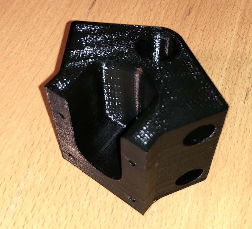
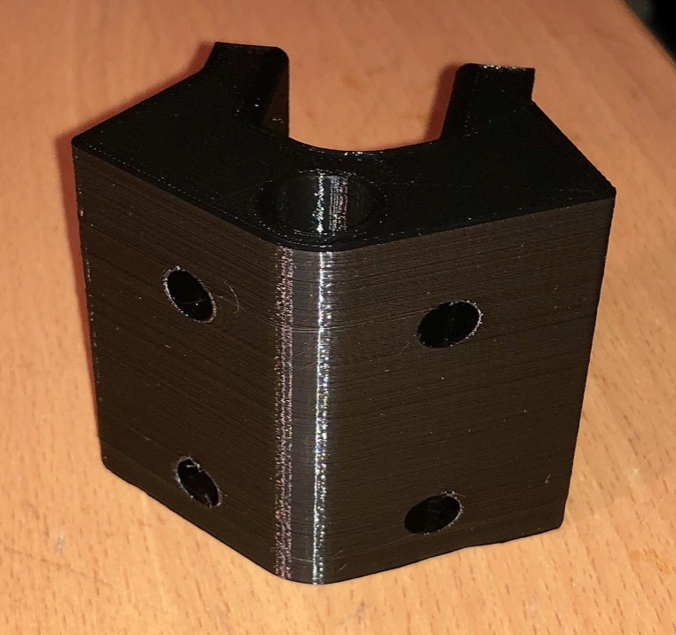
I did print one full size corner piece as a test. While it looks cool I think I found a fatal flaw. There is no way to actually assemble the hexagon. The last piece cannot be inserted. There might be some give in the carbon rods but I don’t like bending things for assembly. We could try a full assembly of the hexagon and slowly pull the end pieces together, but the carbon rods are pretty tight and you need to kind of rotate them to get them to seat in the end piece. I think this would be pretty hard with twelve rods at once.

On the delta I worked on, this was solved by using a 3d printed bar clamp that pulls the rods tight. The initial fitting before tightening these bars is loose enough to allow for some wiggle. We used this method for the vertical rods, but it would be just as effective here.

Here’s the instructions from the “manual”

Here’s all the source. It’s open scad. I also have STEP files you could remix with if you like. Jerry’s design here really works well to keep things rigid, but ease assembly.

Essentially, this would involve:

  • Widening the diameter of the hole

  • Adding a square hole for the tightening bar (clamp) to fit through

  • Two holes for an M3 screw to pull the bar against the rod and clamp it into place
    I’m sure there are other solutions as well.

Or, just use hot glue.

Lorin

image.png

image.png

I wil bring down my delta kit this week. I am pretty pumped to build one as visually they look awesome. For learn to solder events and makerfaires it will definitely get attention for the hive. I also got that creality cr10s for an amazing price on that auvtiom site. I will have fun things to occupy down time with my next surgery.

image.png

image.png

Any parts we can help print? We picked up a second flashforge Creator pro, so we have one dedicated for ABS and one for pla.

image.png

image.png

Brad,
On some other 3D printers you have a similar problem - fitting all the pieces in simultaneously. Basically, you assemble 1 corner and its 2 rods - and then do the same with the other corners. You set them in place and then slowly “tighten” them until the fit - like with a strap around the base. But, if the hole is too tight to allow pushing the rods in place this won’t work. Bigger hole with tightening screws (or glue)?

BTW - I bought some 12" glass hexagons to use as Build Plates. They are at the Hive. There might be a size discrepancy here - or at least we’ll need a mount for the plate.

Another item I noticed when messing with the build plates that I didn’t get a chance to talk over with the original designers… If there are 6 corners then you can build an object that is larger than will fit between the vertical bars. Thus, you can make something in the “cage” that can’t get out. So, we might have to leave one of the verticals out to give an exit.

James

image.png

image.png

That would be hilarious. Like the guy that built a boat in his basement and couldn’t get it out.
I’m thinking one of the corners could be split with a cap to hold the horizontal rods.

I’ll play with it a bit between jobs.

This sounds wacky, where is the source cad files for this?

Delta Printer Design

Last night after the meeting, James, Brad and I briefly discussed the printer design as we understood it. A hex build plate, six single rod vertical supports at the apexes of the hexagon. Cited design flaws; 1) the vertical spacing blocks removal of printed objects larger than edge dimension 2) Carriages are not constrained from rotation, which could allow/cause the effector to tilt.

No one seems to have the original documentation for the printer, so this is mostly guesswork. A few things came out of the discussion…

Conclusion; Retain hex bedplate and design an equilateral triangular base configuration to support three pairs of parallel column rods at triangle vertices. In our judgement a triangle frame is more rigid than a hexagon. Column rod pairs to be aligned with inscribed circumference rather than radially. Design option – add structure to the base to complement / protect the hexagonal bed plate corners projecting beyond the frame triangle. Note, this is secondary to the geometry.

Conclusion; We will collaborate using Fusion 360 as CAD, create a project wiki and post discussion on the board. I’m just getting started with Fusion 360 and will document some parts to begin my education. The project wiki page I created doesn’t show in projects. A little help please, i’m a newb. (be gentle)

Conclusion; We need to document the dimensional geometry of the delta printer before designing individual components of the support structure. One of the first tasks is to document existing structural part dimensions in Fusion 360 to facilitate the printer geometry design.

My Observation: The current inventory of arm rods, base plates, hot ends and motors are part of defining the printer geometry. Further design definition is required to document hot end dimensions including center of gravity and mounting in effector. This will constrain minimum effector dimensions. Selection of arm end attachment to effector and carriage (rod ends or magnet-ball) will further constrain the effector design. Using these constraints the effector geometry can be designed to maximize effector stability as defined in the excellent RepRap Delta_Geometry article.

The effector design, defines the arm spacing which is required to define the carriage. Once the column spacing, effector, arms and carriage are roughed out in dimensions the print envelope can be calculated.

See RepRap – Delta Geometry http://reprap.org/wiki/Delta_geometry

I’d be shocked if no one has a comment.
Now let the fun begin,

Dave

Feel free to email me (bradsa4@gmail.com) with your emails that you use for Fusion 360 and I’ll attempt to setup a shared folder. I know it is possible but I’ve never done it.

I agree on the design principles. I’ll also see about creating a project page on the wiki. (haven’t done that in a while).

My last few weeks have been dedicated to gathering information about Delta Printer design trade-offs. Much of what I learned went into an inverse kinematics spreadsheet. The a link to the inverse kinematics spreadsheet can be found here Inv.Delta.Kinematics and on the project wiki. Download the excel and have fun with kinematics.

Given, only a few parts of what we have are going to work well, there are many things we will need to purchase. Before making any purchases, we need to finalize a design.
My rough estimate of yet to purchase items is between $300 and $600.

Time to huddle and agree on a design.

Critique of what we have:

Through spreadsheet analysis it is observed that the 225mm arms from carbon fiber tube are too short. (restricted print area smaller than the mirrors we have) Arms in the range of 290mm to 320mm give an effective print x,y circle with radius = 135mm. which matches the mirror. Adding the existing rod ends to the existing rods adds < 38 mm which still is not enough.

The carbon fiber tubes proposed for the z corner columns are too soft. (Abraded by a fingernail.) Further, a 1 to 2 lb lateral force at the center point gives a significant bend to the tube. (>8mm) Conclusion: Carbon tubs are too floppy for a good printer. In contrast the same force on an 8mm steel shaft gives .2 mm deflection.

Perhaps we can use the 11.9mm tubes for effector arms. I’d like to go with magnet ball assembly rather than rod ends.

There are three WANTAI 42BYBH610 steppers and three UNKNOWN maker 17HS4401 stepper motors. We will need three matched motors and a fourth for the filament driver.
Specs found on the web show the motors should be OK. We will need to test the motors to determine suitability for torque when micro-stepping.

There are 5 hot end assemblies and 3 partials. Heaters are of unknown wattage.

Dave

Great analysis Dave.
Sounds like we need to pull back and think about what we want to do.
Of course the original thought was to use what we had and build something cool.

Kevin S was going to start building the Delta printer he got from an auction, it looked interesting. Maybe we can use his kit and dress it up with the carbon tubes.

I’m doing this for fun, not for a specific end result.

Heck, I’d be happy to make a large arduino controlled crane.
Maybe a demo of how much weight a carbon truss can support?
We can build some kind of Bucky ball with the carbon tubes.:grinning:

Good times,

Brad

I will keep my eye out on the auction site to see if any other Delta kits pop up for cheap. I figure if I can get a complete kit with the linear bearings and the large build volume for less than 70 bucks or so. I am going to have so much downtime from surgery it would be cheap entertainment to keep playing around with the Delta’s lol.

All,

I have to concur that we should be able to make a fine printer out of what we have. I think we need a Mega/RAMPS board but that should be just about it (well, a few fasteners and a power adapter) and the 3D printed parts. If we want to put $500 into it - we might as well just buy a pre-configured kit. Let’s relook at that…

I tried to use the Kinematics spreadsheet but was left guessing - so clearly I’ll have to do that with parts in hand.

As to existing parts:

  1. There should be 5 identical NEMA-17 motors which I recently purchased. I know Brad has one of them but the rest should be there. These are known to work fine on Delta printers (at least based on spec).
  2. There were previously 3 similar motors. Combined, we should have enough for 2 complete Delta sets.
  3. Agreed, 12mm tubes probably deflect more than their steel cousins. Perhaps they can be reinforced or maybe they are strong enough? If not, then we might as well use the aluminum extrusions that Ryan pointed out and use the “standard” Kossel corners, etc. and call it done. Unless we have some steel laying around?
  4. Agree the “magnetic” solution is cooler. But, can we make an effector assembly with what we have and upgrade that once it works?

James

Why not do both designs? I think that we’ve got two valid philosophies here:

  1. Design from scratch to a set of optimal principles and goals. The benefit of this is a very thorough understanding and control of the design and principles involved. In this case, the learning and designing is as important as the machine.

  2. Use our ingenuity to build from what we have and even allow improvisation. This is right in line with the rep rap ideology and “rep strap” ideas.

In the end, I think we’ll have truly functional printers, either way. The difference is only in the methodology and the details. Plus it would be great to actually have some experimental capability to compare traxxas vs magnets, rod vs rail, extrusion vs other framing, different electronics, etc.

Maybe follow a “core design” regarding area, arm length, height, etc. Then, the designs could diverge into joint designs, materials, etc.

In the end, what do we have to lose except more knowledge?

Lorin

P.S. As far as parts go, the cost will be cheap either way. Additionally, I can kick in many spare parts and do not mind purchasing things with my own cash for use in hive projects. For me, it’s about the experience. For instance, I’d like to try smoothieware or another 32 bit controller, and would be totally willing to pay for that hardware simply to compare its performance with marlin and franklin…

Hi, My name is Dave and I’m a nerd. I’m enjoying the HIVE13 community and would like help it thrive. That said, when I dive into a subject, it may annoy others. Please forgive me in advance.

Learning Delta Printer design and learning enough to improvise like a jazz musician is what I’m up for right now. To that point, I’d like to build a personal copy of a Delta printer design for myself.

Following the learning track started with kinematics fundamentals, to explore why existing design choices were made. I’ve been asking questions and reading critiques to make our own design refinements.
My intent would be to make a printer that performs as well as or better than the existing marketplace printers within a reasonable budget. It doesn’t need to be different from existing designs, it just needs to be well thought out. Not a wrote copy without understanding the choices implicit in the design. If a design choice is good, I’d copy. (imitation is sincere flattery). In the longer run, this printer would be an experimental platform for further improvements.

With that intro, let me further propose some design objectives.
Print envelope Base circle Radius >= 130mm, Z >= 310mm Print step resolution (accuracy) X,Y,Z < 0 050mm, Print speed capability in X,Y,Z >200mm/sec
Heated bed, multi material capability. One material hot end design to start, then add more feeds to the head in stage 2.
Micro-stepping capability with good wave form tuning for a quieter motor and strong positioning performance. This would imply a highly capable controller and power chips for motor control.

What do you all think about design objectives?

A shared bill of materials with collaboration on parts sourcing can help control the budget. We should plan for repair spares in the purchases.

Optional modular alternatives in the bills of material are part of my past product design experience.

Prototyping design elements and testing for quantifiable performance makes good sense. (Confession, I come at product design with a six sigma product reliability background. Though have McaGyvered many a project… this needs more than duct tape and coat hangers. Again, please forgive me, if I nerd my way into the details.)

The existing parts that are of concern to me specifically are:

  1. Rods and rod ends, Arms ~260mm could print the entire 130mm radius hex mirror build plates we have. Rod ends work, they just take more effort to install/remove.
  2. Carbon fiber tubes as vertical columns are a flexibility concern. X,Y acceleration vectors could drive significant displacement which would be errors in a print. There are too many unknowns to run the carbon tubes displacement or harmonic vibration calculations like you can with steel rods, but being able to easily bend a tube with one finger an experienced gut says the tubes would flex in operation. Probably would not harmonically resonate with higher stepper rates, but would move.
    For those reasons, I wouldn’t choose to use the rod ends or carbon tubes in my own printer build.

I’m willing to buy and contribute parts to help test designs and most likely build along at home too. (May well wind up buying a Prusa I3 clone kit to be able to print parts.)

Along that line, I’m in with prototype exploration of 32 bit control boards and motor power control chips for microstepping. Smoothieware seems to be a good candidate, maybe there are others. Plenty to research and discuss. Magnetic joint design is also something to prototype.

OK. Now you all will certainly let me know what you think.
Best Regards,
Dave

PS - The kinematics spreadsheet is built from the kinematics in the two papers posted on the project wiki. Steve Graves and Deepak Kandepet did very good work. I’ve tried to use their terms in the calculations. If you have questions or corrections or would like a conversational walk through, drop me a private note.
I appreciate all of Dave’s research.
It seems like this is scope creeping into another beast.

I agree on the vertical carbon tubes may not the be best thing.

We can get hardened steel 12mm shafting for about $8 each for 13" long. If we bury them 1.5" into each end block that leaves us with around 10" of Z. Of course it will probably be more like 8" after the stuff gets assembled. Heck even if it is only 6" high that may be cool.
http://a.co/blWRcJF

And then get 12mm bearings for about $4 apiece.
http://a.co/i2PjJXL

Or we could get a 1’ length of 1" diameter PTFE rod and make our own bushings.
https://www.usplastic.com/catalog/item.aspx?itemid=25676&catid=720

I’m leaning on just working on a smaller build volume instead of trying to get longer rods.
What can we build with what we have?

All design decisions are a trade-off. Using the existing arms between 225mm and 260mm long depending on ends and a Z travel of 300mm and base triangle of 265mm limits the print footprint to an odd pattern and allows for a cylinder height of around 30mm. Note: the delta print envelope is roughly a cylinder topped with a cone.

Deflection calculations on 8mm rods would indicate a pair are stiff enough for the guides. An additional external frame would make the structure more robust. I’d go with 8mm rods of > 750 mm length which are priced at $10 to $16 each for 1000mm lengths depending on source. 6 to 10 Linear ball bearings for these in lot quantities are very low priced. eBay and Aliexpress.

Building a printer will require effort. I’d prefer to get something that I want to use out of the exercise. I’m planning to pitch in for the cost of materials, sweat the details and go slow to achieve that end.

Dave

Sounds like there is some energy to work on this.
My mother has taken a turn for the worse and I will probably be travelling down to help her.
With other obligations (work, Cincinnati family, etc.) I will transfer the project lead to Dave or James.
I’ll be happy to chip in when I can but I have to back out of active participation.

Let me know who would like to take the wheel.

Thanks,

Brad

I’m in.

I’m building 2.0 of my delta design, Athenasius. I’d like to do it along side this project and also contribute to the Hive’s printer. I’ll also bring my current delta down for a while if it would be useful as a reference. I can point out everything I am proud of and everything I regret.

So, here are some things that really helped me get this done over the past year:

  1. Start from an effective and well documented design. I used the MTU-MOST delta.

  2. Where possible, use components that are ubiquitous among 3D printer designs, such as 8mm linear rods, M3 screws, 806zz bearings, GT2 belting, etc. This makes everything easier to manage, cheaper to source, and easier to fix.

  3. Compile a detailed B.O.M. before sourcing everything and going to town with suppliers…

  4. Avoid weird dimensions. Even round numbers are good, and having things like distance between arms match some established designs is handy if you want a reference from open source.

  5. Don’t pay too much attention to forums. A LOT of discussion on rep-rap and other forums leads one to believe that it’s hopeless unless you make a machine your frame out of a solid block of magnesium, use mitutoyo granite surface plate as the bed, make nozzles from sapphire, and be so silent it is only audible within an anechoic chamber. It’s not a space shuttle, and printing at 300+ mm/second on these machines yields diminishing quality of the prints.

  6. For critical components, sometimes cost is not the primary factor. I paid 30% more to get linear rods that wouldn’t be bent the moment they arrive (that happens a lot with cheaper ebay sellers). I’d rather use misumi and save myself the grief of straightening a rod to fit a linear bearing without binding. Likewise with crappy electronics.

  7. Patience. Willingness to do something over again (maybe 3+ times).

Anyway, I agree with Dave fundamentally on most points. I’m also a fiddly perfectionist who thinks too much… And furthermore, I’m a bit outlandish with my goals sometimes. Well, we’re all special flowers at hive13 and that’s why I like doing things here.

Lorin

Sounds awesome. I’d still like to be involved but I just don’t think I can “manage” the build.

Good times.

Brad